

 Reply With Quote
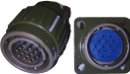
Anyone used these bulkhead connectors?
Near the bottom of this page -
Sensors and connectors
Looks like a tidy way to get my wiring through the firewall and make is easy to disconnect.
Callum


power up the ECU on the bench, install megatunix and display the tooth logger tab, put a white dot on the relevant tooth, put another white dot one ONE of the sensors, hookup the dizzi with one of the G sensors wires in, rotate the tooth back-and-forth over the marked sensor, you should get a trigger signal, try the non-marked sensor, swap the wiring between the G sensors and try again.
Also, there's this handy diagram in the MSextra manauls.
here: MS2-Extra 24 toothed Manual
and here: Megasquirt-3 MS3 Trigger Wheel
Anyone used these bulkhead connectors?
Near the bottom of this page -
Sensors and connectors
Looks like a tidy way to get my wiring through the firewall and make is easy to disconnect.
Callum
BallPencil, at 28kpa, a 7kpa difference is 25%. So having to shift by 30% to make up for it isn't unfeasible. I personally would order the parts for, and use, the unit designed to go in the MegaSquirt, as it will just work, and spending a few dollars on that is a lot cheaper than rebuilding a motor again because you tried to rip the top off a couple of pistons (need proof?)
As for the Mil-Spec plugs, we use them at work. They are pretty damned robust, but look ugly as sin. DIY Autotune do plastic waterproof bulkhead connectors which may look neater, and may allow for thicker gauge wiring.
Cheers, Owen
1977 RA28 with 1JZ-GTE (Was 18R-GTE)
Lancer EVO Brakes into old Celica/Corolla/Corona
Doing the things that aren't popular... cause being popular and being good are often distinctly different.
The connectors Callum linked to support:
19-pins - 10 Amps per pin
36-pins - 4 pins @10 Amps each, 32 pins @5 Amps each
50-pins - 4 pins @10 Amps each, 46 pins @5 Amps each
(at least those are the pin counts that might be useful to me).
Yeah now that i read it a few times it makes sense now. Doesnt matter which you use, as long as you enter the tooth #1 angle correctly. there will be a 180deg (cam, so 360deg crank) difference in the number you use, thats all. And the number used for tooth #1 is obviously going to be crank deg.
Originally Posted by thechuckster

Those connectors can't be the traditional mil-spec metal housing versions. Ignoring shipping, they're about 20% of the cost of the metal ones. I suspect they're plastic (which is not a bad thing) and not actually military spec.
Also isn't clear whether it includes the terminals, which is usually half of the cost of the connector. the fact they don't sell the terminals seperately makes me think they're included.
edit: I've got some of those 22-pin bulkhead connectors you're talking about Oman... They use weatherpack terminals (20A each!) and are about 10cm in diameterThey're freaking huge, and look way out of place on a firewall.
I use geniune automotive Tyco bulkhead connectors. They're plastic, compact, and look similar to the ones that Calum posted.
Ok guys my MS2 with 3.57 board showed up today from DIYautotune and it came with no instructions at all from them. So i have a CAS a IAT sensor a coil an ECU and a wideband o2 sensor with no idea how it all goes together. Does anyone on here know where instructions can be found for wiring up an 18rgeu with these components?
Cheers
Simon
Kiwi back yard mechanic/fabricator/machinist/welder
http://www.toymods.net/forums/showth...t=tt1uzfe+RA23]
Megasquirt MSEXTRA Manual Index
Setup - VR sensor
1) Set the crank at 20BTDC
3) Make sure the rotor arm points towards the correct contact in the distributor cap
4) Bolt down the distributor
5) Turn engine backwards until the pip (trigger tooth) lines up with the VR sensor
6) Measure angle BTDC (+/- 10 degrees is good enough) at the crank
7) Enter measured angle in "Trigger angle" of Spark Settings
8) Enter "Fixed angle" to 10 degrees this tells the ECU to ignore the spark map and hold it to the Fixed Angle.
9) Start the engine
10) Adjust "Trigger angle" until the timing light is at 10 degrees
11) Set "Fixed angle" to -10 , this tells the ECU to run from the spark map again.
12) Start tuning
(some of the above may vary slightly for the MS2 extra software but the principles are the same)
Start here: Megasquirt 2 - External wiring layoutsSo i have a CAS a IAT sensor a coil an ECU and a wideband o2 sensor with no idea how it all goes together. Does anyone on here know where instructions can be found for wiring up an 18rgeu with these components?
Would suggest making loom from scratch (except using any existing sensor plugs that are still good)
notes:
- CAS - i presume you have an 18RG dizzi, in which case you open it up and disable the mechanical and vacuum advance
- O2 wideband - can be within several feet of engine, weld on the threaded bung in a sensible spot ensuring it's not facing upwards so moisture can get into the sensor (read the manual carefully about earthing)
- IAT - remove cold-start injector, block off the port on the rail that supplies it with fuel, find small piece of 5mm thick alloy to cover hole in plenum, drill hole in same plate to let you screw in the sensor
- TPS - 18RGUE items is probably a idle/wot switch only, will probably need a proper TPS that has variable resistance for throtttle movement.
- fuel pump - the AFM had a switch in it to enable it (via the circuit-opening relay). Wire ECU so it drives/controls the circuit-opening relay.
Thankyou very much for that. An extremely helpfull reply!!! I also bought a coil off them with built in ignition driver
Simon
Kiwi back yard mechanic/fabricator/machinist/welder
http://www.toymods.net/forums/showth...t=tt1uzfe+RA23]
Ignore that last bit i think i have found instructions.
IGN-1A Race Coil DIYAutoTune.com
Kiwi back yard mechanic/fabricator/machinist/welder
http://www.toymods.net/forums/showth...t=tt1uzfe+RA23]
How is everyone going?? How are the MS's running anyone done any dyno tuning yet?
Just finishing up the engine loom. Got hold of a Deutsch connector so the engine loom is quick disconnect. Should make removing the engine just a tad easier.

Last edited by drew22; 05-02-2012 at 12:54 AM.
drew, nice and neat engine loom. I like the idea of colour-coding and matching the COP and injector plug for each cyl. Are there other connectors for your CAS? (am assuming the two plugs at the right are for CLT and IAT)
btw: can you provide some info on the cloth-like cable sheath? I'd like to get some of that stuff for my RA65 loom.
Thanks C. The two connectors on the right are for the Cas and the alternator. I need to add in wiring for the TPS,CLT,CLT Guage,Oil pressure light and IAC. The IAT is a part of the air box on my AE82 so ill build that into the Body loom.
With the sleeving you need to look at a product called PET Expandable Braided Cable Sleeving its quite good stuff rated to 125 degC so no probs using it in the engine bay. Just not near the exhaust
I brought mine off ebay by the meter. The guy is based in QLD and sells in 3mm, 6mm, 9mm, 12mm diameter to whatever lengh you want.
3sgte, hmm im struggling to get mine to start and then idle smoothly. Stupid XF ICV i think its super dirty so i gotta clean it out. It will only open at at least 80% duty and wont close 100% either. So pretty sure its really dirty inside.
Cranking, not sure what to do about cranking PW% yet. Tried a few things but it just wont start up directly. It backfires, then if i floor it for flood clear, it will sometimes start! Ive been trying the recommended ones in the MS manual on MS3efi. Any ideas for idle VE? Its set to about 60 atm, but i think its too high, the closed loop O2 correction is adjusting it heaps and causes a very inconsistant idle. I have 1000c injectors. Possibly even double required because i disabled the close loop correction and it went to about 10.5 AFR!
Also, is it normal for the TPS position to jump to about 4/5% during cranking? My POS TPS also fluctuates during operating, its like when it gets hot, it drops about 1-2% in value while idling lol, so its at like -2%!
I left the cranking pw% at the standard ms3 setting, worked quite well also disabled closed loop. Block the ICV and set a nice base idle on the throttle blade just to get you going then have a crack at getting the ICV going.
If it hunts around at idle try the idle timing tab, lock in a timing value that the engine is happy to idle at.
Whats is your injector PW at idle?
Did about 3000kms in mine with the ms3 it was quite normal for the TPS value to drop 2% when fully warmed up.
 Posting Permissions
 )
)

Bookmarks