
 Reply With Quote
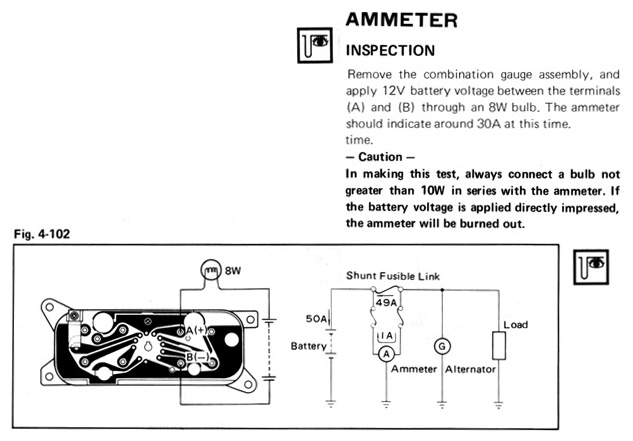
The test circuit is the one on the left in the figure. The one on the right is how the amp meter is connected in the car. Just make sure you follow the warning about globe wattage.


I'm having trouble wiring the original ammeter gauge in an RA28.
I've tested the gauge following the instructions on page 4-40 of the Body Repair Manual and it works perfectly.
Full RA28 wiring diagram here
I've replicated the wiring diagram as best as I could, but the ammeter doesn't move when I turn on the accessories/electric fuel pump, start the car, or idle.
I tested the wires for continuity with a multimeter, and they're all fine.
My understanding from the wiring diagram is that for 50A, 49A would go through the fusible link, while 1A would go through the ammeter. Do the wires to the ammeter and the fusible link need to be a specific size?
I'm not sure what I'm doing wrong here. Any help would be appreciated
Last edited by andrewzuku; 29-03-2022 at 06:11 AM. Reason: Updated broken links
The test circuit is the one on the left in the figure. The one on the right is how the amp meter is connected in the car. Just make sure you follow the warning about globe wattage.
Fast, Cheap, Reliable
You can only ever have two..
I didn't have an 8W bulb, so I tested with a 5W bulb. The ammeter needle moved about 30%. A multimeter in place of the ammeter shows 0.35 Amps - which all makes sense. The RA28 Ammeter should be at Full Scale Deflection (FSD) with 1 Amp.
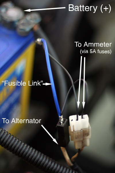
My car didn't have a fusible link in it when I bought it, but the 5A fuses and wiring to the gauge cluster is already in place in LT's.
In place of the fusible link I used some normal wire, 4 AWG sizes smaller than the main (thick white) wire and took the reading either side of that. With the alternator unplugged and the high beams on I was able to get the ammeter to move slightly. So I just need a properly calibrated shunt/fusible link.
I phoned my local Toyota parts dealer, but they can't get the original fusible link anymore.
RA28 Fusible Link:
90982-08027 - w/o ammeter (LT)
90982-08045 - with ammeter (ST, GT)
So instead, I'll just use a generic fusible link, and then take the ammeter's reading from either side of a shunt.
Jaycar sell a 50 Amp / 50 mV shunt for $12.95: http://www.jaycar.com.au/productView.asp?ID=QP5412
They're cheaper on ebay, but then I'd have to add postage and wait 2 weeks.
I'll let you know how I go
Last edited by andrewzuku; 04-09-2012 at 09:12 AM. Reason: forgot to mention my temporary fusible link
to hook it up is easy but i never hook ammeters up as they can make the car catch on fire heheeheh
basically find the main power to the ignition switch/car power
most toyotas it will be a white wire
so power from battery goes to in terminal on ammeter
and the out goes to the rest of car white wire which powers everything
basically goes in series and measures the current draw thru the whole system
problem is most ammeters measure up to 40 or 60 amps
if car is factory and untouched 60amps is ok
one u add thermo fans elect fuel pump etc etc efi etc etc
the car might use more than 60 amps
this is when ammeters get hot and melt and burn and car catches on fire
replace it with volts gauge
Hey, thanks for the suggestion, but...
Wiring the original RA28 ammeter in series with the full current will burn it out.
What you've said makes sense for an ammeter with a built-in shunt (TA22 Ammeter, and most after-market ammeters).
After a fair bit of reading over the last couple of days, I've learnt that Toyota were clever with the RA28 Ammeter gauge. You can see from the diagram at the top of this thread, and from the RA28 Wiring Diagram that the ammeter runs in parallel with the fusible link and only takes 2% of the current from the main white wire.
Here's an article that explains it better than I can...
Sizing a Shunt to a DC Ammeter
Last edited by andrewzuku; 04-09-2012 at 07:43 PM. Reason: TA22 Ammeter
ok cool
so i guess its just scaled differently then on the readings to mak eit look like its reading all the current
The TA22 Ammeter has +50 and -50 amp markings, but the RA28 Ammeter only shows (+) and (-).
The RA28 Ammeter is actually a 1 Amp gauge.
When properly calibrated, the shunt fusible link should allow 2% of the current through the ammeter. This means it's effectively showing +/- 50 Amp at Full Scale Deflection
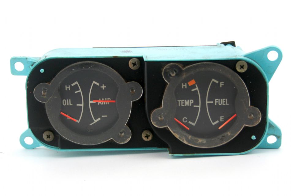
Here's a photo of my actual gauge cluster...
andrewzuku,
A little off topic, my RA23 has two lights for oil and battery not gauges? What model is your RA28?
Fast, Cheap, Reliable
You can only ever have two..
Hey Flex,
Mine's an LT like yours, which originally had the warning lights, but I managed to find the GT gauges about 3 months ago.
The oil gauge was just a matter of replacing the oil pressure switch on the engine with an oil pressure sender. I'm only just now trying to connect the ammeter.
There's a link in my signature to my build diary with a bunch of photos
Ok, I tried a 50A/50mV shunt from JayCar, but it does the same thing as my temporary fusible link.
for the 19 Amps that the high beams draw, I'd like to see 0.38 Amps (2%) at the gauge. Instead I get 0.01 Amps. If I measure right at the shunt in the engine bay it's about 0.20 Amps.
The only thing I can think to try is to fine-tune the size of the shunt/fusible link and wire going to the ammeter until it takes 2% of the current.
Surely there's a formula to work out the size from known lengths of wire.
-- EDIT --
Or perhaps I should be thinking in terms of resistance?
The multimeter reads 2.1 Ohms when measured at the plug for the ammeter in the engine bay.
What resistance would I need across the fusible link, so that the ammeter see's 2% of the current? Is it as simple as multiplying 2.1 x 2% = 0.042 Ohms?
Last edited by andrewzuku; 19-09-2012 at 05:02 PM. Reason: Extra info
There is a substantial amount of DIY information here...
http://forum.ih8mud.com/diesel-tech-...y-78-bj40.html
I don't know if it answers your question, but it might help
Cheers... jondee86
Hey Jondee, Thanks for the link.
From what he was saying, it looks like the ammeter never really moved much - even from factory. That makes sense after reading about resistance and playing with this calculator:
http://chemandy.com/calculators/roun...calculator.htm
Then I had a thought...
Since a wire's resistance increases with it's length, why don't I just run wire the same gauge as the fusible link (16 AWG?) in parallel to the ammeter. If I use 49x longer wire than the fusible link, that should give me the 49:1 ratio (or 2% current to the ammeter).
There may be some obvious reason I'm not seeing why this won't work, but I'll let you know how I go
This sounds right to me. A 0.042 Ohm resister with 50A passing through will have a voltage drop of 2.1V which when in parrallel with a 2.1 Ohm resistance will also pass 1A giving a total of 51 Amps (50 through shunt and 1 through meter).Originally Posted by andrewzuku

Have you measured the resistance of your fusible links? Do you have an ammeter to test the current from the battery to the fusible link? Also high current draw from the battery will only happen when the alternator is not charging (ie motor off) as the alternator will be supplying all the accessories with minimal current flowing back to the battery to top up the charge.
Glen
Hey Glen,
With the high beams on (and car not running), I get 19 Amps measured between the battery and fusible link.
I posted this same problem up on 1stgencelica.com, and I'm about to try:
- 100mm of 16 AWG wire as my fusible link
- 4900mm of 16 AWG as a loop to the ammeter
My theory is that since they'll both be 16 AWG, the difference in length will create the 49:1 resistance ratio.
Don't forget about the resistance across the guage itself. That will be added in series to your 4900mm of wire. If your wire is good quality with low voltage drop over the length the guage may have more bearing on the ratio than the wire.
Glen
 Posting Permissions

Bookmarks